

Sand Casting Versus CNC Machining: Which Fits?
A valve body that costs too much to machine from solid stock can be an excellent casting. Equally, a small precision adaptor may not justify a pattern, however attractive its unit price looks on paper. Sand casting versus CNC machining is therefore not a simple choice between an older process and a more precise one. It is a sourcing decision shaped by geometry, annual volume, tolerance, alloy, finishing requirements and the cost of failure in service.
For OEMs and industrial buyers, the best route is often the one that delivers the required performance with the lowest total landed cost, not the lowest quoted piece price. This means assessing manufacturing allowances, inspection requirements, machining time, material yield and the stability of repeat production before releasing a purchase order.
Sand Casting Versus CNC Machining: The Core Difference
Sand casting forms a component by pouring molten metal into a sand mould made from a pattern. Once the metal has solidified, the mould is broken away, gates and risers are removed, and the casting is cleaned. Where critical faces, bores or threads are required, these are normally machined afterwards.
CNC machining removes material from bar, billet or a preformed blank using programmed cutting tools. It is highly controlled and well suited to precise dimensions, repeatable features and fine surface finishes. For brass and bronze components, it can produce accurate threads, sealing faces, ports and interfaces directly from solid material.
The essential distinction is material use and shape creation. Sand casting creates a near-net shape with relatively little metal removed. CNC machining begins with more material than the finished part needs and cuts it away. This difference drives the cost model, especially for larger parts or designs with substantial cavities and changing wall sections.
When Sand Casting Makes Commercial Sense
Sand casting is usually the stronger option where the component is relatively large, geometrically complex or required in medium to high quantities. It is particularly effective for bronze and copper alloy bodies with internal passages, flanges, bosses and varied wall thicknesses, such as pump housings, valve bodies, pipe fittings and fire-protection components.
A casting can place metal close to its final form. That reduces machining time, raw-material waste and tool wear compared with producing the same body from solid bar or billet. When copper alloy prices are a significant part of the part cost, improved material yield has a direct commercial benefit.
Sand casting also gives designers more freedom to create features that would be expensive or impractical to mill from solid stock. Internal flow paths can be produced with cores, while ribs and external profiles can be incorporated into the mould. This is useful where fluid performance, weight control or a compact installation envelope matters.
The trade-off is that sand castings need sensible design allowances. Draft angles help the pattern withdraw from the mould. Corners require radii to support sound metal flow. Wall thickness must be controlled to reduce risks such as shrinkage, porosity or distortion during cooling. A capable foundry will review these points before production rather than relying on inspection to find problems later.
Pattern cost is another consideration. A simple pattern may be modest, but multi-part tooling and complex core boxes increase the upfront investment. This cost is spread across the production run, making sand casting less attractive for a one-off component unless the savings in material and machining are substantial.
Tolerances and Surface Finish
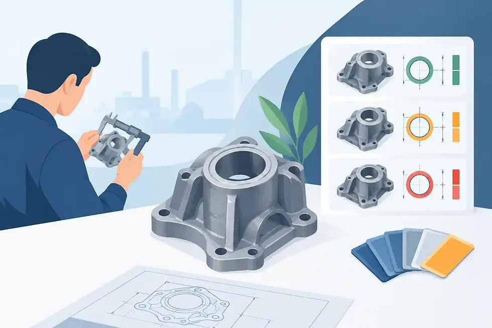
As-cast surfaces are not equivalent to machined surfaces. Sand mould texture, alloy behaviour and casting shrinkage mean that dimensional variation is higher than for CNC-machined features. Critical dimensions should be identified clearly on the drawing, with machining allowances provided where necessary.
For a valve or pump component, this commonly means machining the sealing faces, threaded ports, bore diameters and mounting locations after casting. Non-critical outer surfaces can remain as-cast. This approach protects functional performance without paying to machine areas that add no value.
Where CNC Machining Is the Better Choice
CNC machining is often the most efficient choice for low volumes, prototypes and parts with demanding dimensional requirements throughout. There is no need to manufacture a foundry pattern first, so production can begin quickly once the material, programme and fixtures are approved.
It is well suited to smaller brass fittings, threaded adaptors, precision stems, electrical components and machined inserts. Components requiring close tolerances, concentric bores, accurate thread forms or fine sealing finishes are also strong candidates. Repeatability is high when the process is supported by controlled tooling, stable programmes and in-process inspection.
For a small batch, machining from bar stock can reduce project risk. Design changes can often be made in the CNC programme without writing off casting tooling. This is valuable during product development, field trials or early market launch, when the final geometry may still change.
However, machining time rises quickly with part size and complexity. Deep pockets, large material removal volumes and multi-axis operations increase cycle time. Material removed as swarf has residual value, but it does not carry the same value as metal retained in the finished component. For a sizeable bronze body, this can make an all-machined approach commercially uncompetitive at scale.
Cost Is a Volume Calculation, Not a Process Label
Buyers sometimes assume casting is always cheaper at high volume and machining is always cheaper at low volume. That is broadly true, but it is not sufficient for a reliable decision. The break-even point depends on pattern cost, part weight, alloy price, machining content, casting yield, rejection risk and the number of production releases expected over the life of the programme.
A small, straightforward component may remain cheaper to machine even at considerable volume because the cycle time is short and casting tooling would add unnecessary cost. Conversely, a heavy component with internal cavities may justify casting at relatively modest quantities because the material saving and reduced cutting time are so significant.
A useful quotation comparison should separate one-off costs from recurring costs. Pattern and core tooling should be visible rather than buried in the unit price. The supplier should also state whether machining, pressure testing, surface treatment, marking, packing and inspection documentation are included. Comparable scope matters more than a headline unit price.
Material Performance and Process Control
Both processes can produce dependable brass, bronze and copper alloy components when alloy selection and process control are correct. The required material should be defined by the application, whether resistance to corrosion, pressure capability, wear behaviour, machinability or compatibility with potable water is the priority.
Casting introduces metallurgical controls that are not present when machining certified bar stock. Melt chemistry, pouring temperature, mould preparation and solidification must be managed consistently. The foundry should control heat identification and verify composition as required by the specification. For pressure-retaining bodies, soundness is especially important, and testing may include hydrostatic or pneumatic pressure tests where appropriate.
Machining introduces its own controls. Tool condition, workholding, cutting parameters and datum strategy all affect accuracy and surface quality. A part can meet individual dimensions yet fail to assemble correctly if the relationships between features are not controlled. First-off approval, gauge planning and traceable inspection records provide useful protection for critical programmes.
The Practical Middle Ground: Cast Then Machine
For many industrial components, the best answer is not sand casting or CNC machining. It is sand casting followed by CNC machining of defined functional areas. The casting delivers efficient material use and complex geometry; machining delivers the dimensions, threads and sealing surfaces needed for reliable assembly.
This hybrid route is common for valve bodies, pump casings, manifolds and custom copper alloy fittings. It gives procurement teams a route to scale without accepting unnecessary risk on critical interfaces. It also allows engineering teams to specify tolerances where they matter instead of applying costly precision to the entire part.
At Tan Tasa UK, this type of manufacturing review is most valuable before tooling is committed. Early discussion of alloy grade, drawing tolerances, annual demand, testing requirements and packing expectations can prevent a technically correct part becoming an expensive sourcing problem.
What to Include in Your RFQ
A clear request for quotation speeds up process selection and improves price accuracy. Provide a dimensioned drawing or 3D model, alloy specification, annual and initial quantities, tolerance requirements, critical-to-function features, required tests and any surface finish or marking requirements. If the part replaces an existing casting or machined item, include known failure modes and assembly concerns.
Also identify forecast demand rather than only the first order quantity. A supplier can make a better tooling and production recommendation when it understands whether an initial batch of 500 parts is a one-time requirement or the start of an annual programme of 20,000.
The right manufacturing route should leave you with more than an acceptable component. It should provide a repeatable supply position, clear inspection controls and a cost structure that remains competitive as your demand changes.


Comments